
Posts

Showing posts with the label H-plane T

AM TRANSMITTER

Image
AM TRANSMITTER In an  AM  ( amplitude modulation )  transmitter  the amplitude (strength) of the carrier wave is varied in proportion to the modulation signal. In an FM (frequency modulation)  transmitter  the frequency of the carrier is varied by the modulation signal. There are two basic configuration for transmitters. High level modulation low level modulation  High level modulation In high power modulation signal,the carrier voltage is modulated at highest power level.the require power level is obtained by class c power amplifier.The block diagram of high level modulation as shown in fig(a). low level modulation In the low level modulation system, the carrier is modulated at low power level and the carrier power is subsequently raised to the desire level in the class B amplifier . transmitters using high power level are widely use at present .The block diagram of high level modulation as shown in fig(b). ...
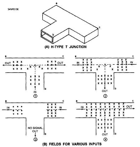
H TYPE T JUNCTION (H PLANE TEE)

Image
H TYPE TEE JUNCTION An H type T junction its so in figure (A) it is called an  H type T Junction because the long axis of the b r is parallel to the plane of the magnetic lines of the force in the waveguide full stop again comma for simplicity, only  the E lines    are show in figure.It X indicates an E line Moving away from the observer.  Each dot indicates an E line is moving toward the observer. In view (1) of figure(B),the signal fed into arm b and in phase outputs are obtained from the a and c and the output signal is obtained from the b arm because the fields add at the junction and induce E lines into the b arm. If 180 degree out of phase signals are fed into arms a and c, as shown in view (3),no output is obtained fro b arm because the opposing fields cancel at the junction .if a signal is fed into the a arm, as shown in view (4), outputs will be obtained from the b and c arms .the reverse is also true. If a signal is fed into the c arm, ...

E TYPE TEE JUNCTION

Image
E TYPE T JUNCTION An e type t junction as shown in fig.1.It is an  E type T junction because the junction arm extends from the main waveguide in the in the same direction as the E field in the waveguide. fig.1. In the E type t junction  the E field for various input as show in fig.2.The  E type T junction with inputs fed into the various arms.The magnetic  lines that always present with an electric field have been omitted. In view (k), the input is fed into arm b and the outputs are taken from a and c arms. when the E field arrives between points 1 and 2 ,point 1 becomes positive, and 2 becomes negative. The positive charge at point 1 induce a negative charge on the wall 3.The negative charge at point 2 induces a positive charge  at point 4 .These charges cause the fields to form 180 degrees out of phase in the main waveguide; therefore, the outputs will be 180 degree out of phase with each other. In view l, 2 in phase inputs of equal amplitud...