AM TRANSMITTER

Image
AM TRANSMITTER In an  AM  ( amplitude modulation )  transmitter  the amplitude (strength) of the carrier wave is varied in proportion to the modulation signal. In an FM (frequency modulation)  transmitter  the frequency of the carrier is varied by the modulation signal. There are two basic configuration for transmitters. High level modulation low level modulation  High level modulation In high power modulation signal,the carrier voltage is modulated at highest power level.the require power level is obtained by class c power amplifier.The block diagram of high level modulation as shown in fig(a). low level modulation In the low level modulation system, the carrier is modulated at low power level and the carrier power is subsequently raised to the desire level in the class B amplifier . transmitters using high power level are widely use at present .The block diagram of high level modulation as shown in fig(b). ...
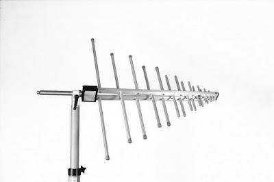
LOG PERIODIC ANTENNA

LOG -PERIODIC ANTENNA

The log periodic antenna show in fig 1.is a multiple - element antenna the uses an entirely different principle than that of the yagi antenna.It provides good gain and wide bandwidth ,although the achievable gain is not as high as a yagi can provide for the same as antenna.The log periodic antenna consists of an array of dipoles extended along a horizontal axis. The length of each dipole is shorter than the dipole preceding it.All dipoles are connected and transmission line is connected to the shortest dipole.Maximum radiation is from the small end.


ADVANTAGE

-wide bandwidth

-same back to front ratio.

-It is design to work across wide range frequency.

DISADVANTAGE

-The VSWR performance not so good.

-low gain

APPLICATION 

-It is use in television

-It is use to measure EMC (electromagnetic compatibility) 

VIDEO OF LOG PERIODIC ANTENNA


Comments

Popular posts from this blog

AM TRANSMITTER

TIME DIVISION MULTIPLEXING

Psk modulation block diagram .