Posts

Showing posts from December, 2017

AM TRANSMITTER

Image
AM TRANSMITTER In an  AM  ( amplitude modulation )  transmitter  the amplitude (strength) of the carrier wave is varied in proportion to the modulation signal. In an FM (frequency modulation)  transmitter  the frequency of the carrier is varied by the modulation signal. There are two basic configuration for transmitters. High level modulation low level modulation  High level modulation In high power modulation signal,the carrier voltage is modulated at highest power level.the require power level is obtained by class c power amplifier.The block diagram of high level modulation as shown in fig(a). low level modulation In the low level modulation system, the carrier is modulated at low power level and the carrier power is subsequently raised to the desire level in the class B amplifier . transmitters using high power level are widely use at present .The block diagram of high level modulation as shown in fig(b). advantage AM sign
LOG PERIODIC ANTENNA

Image
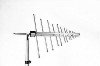
LOG -PERIODIC ANTENNA The log periodic antenna show in fig 1.is a multiple - element antenna the uses an entirely different principle than that of the yagi antenna.It provides good gain and wide bandwidth ,although the achievable gain is not as high as a yagi can provide for the same as antenna.The log periodic antenna consists of an array of dipoles extended along a horizontal axis. The length of each dipole is shorter than the dipole preceding it.All dipoles are connected and transmission line is connected to the shortest dipole.Maximum radiation is from the small end. ADVANTAGE -wide bandwidth -same back to front ratio. -It is design to work across wide range frequency. DISADVANTAGE -The VSWR performance not so good. -low gain APPLICATION  -It is use in television -It is use to measure EMC (electromagnetic compatibility)  VIDEO OF LOG PERIODIC ANTENNA

satellite communication

HORN ANTENNA

Image
HORN ANTENNA When a waveguide is terminated by a horn, such as many of those are shown in figure .1 the abrupt discontinuities  that exist at the edge are replaced by a gradual transformation. if incidence matching is correct, all the energy travelling forward in the waveguide will be radiated. Directivity will also be improved and diffraction reduced . There are several possible on configuration; three of the most  are show here. The  sectorial   horn  flares are out in the One Direction only and is the Is the equivalent of pillbox parabolic reflector. The pyramidal horn flares out in both direction and has the shape of truncated pyramid. The conical horn is similar to it and it does logical termination for circular waveguide if the   φ  figure (a). is it too small, resulting in a Shallow horn, The wave front leaving the horn will be spherical rather than plain, and the radiated Beam will be not directive. fig.(1) The flare angle is given by φ = tan -1 (h/2L)

YAGI ANTENNA

Image
  YAGI ANTENNA  The location  and the length of the director and reflector element are critical, and therefore there can be more than one of each. in practice , adding more reflectors has little benefit ,so  nearly all   arrays have only one reflector element. the Yagi Uda array or simply the Yagi antenna has a single    driven element usually a ƛ/2 Dipole  or folded dipole as show in figure. the reflector is 5% longer than the driven element and space between 0.15 to 0.20 ƛ  Behind the driven element. S ingle director element, 5% shorter than the driven element is space the same distance on the other side to complete the basic Yagi antenna.Due to the relatively large physical dimensions of that elements and their spacing, the Yagi antenna is rarely used for the frequency below the VHF band.     fig (1) basic four element YAGI design fig 2 radiation pattern  Advantage -High gain -High front to back ratio - high Directivity    Disadvantage -Gain is

H TYPE T JUNCTION (H PLANE TEE)

Image
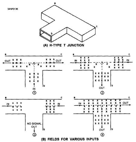
H TYPE TEE JUNCTION An H type T junction its so in figure (A) it is called an  H type T Junction because the long axis of the b r is parallel to the plane of the magnetic lines of the force in the waveguide full stop again comma for simplicity, only  the E lines    are show in figure.It X indicates an E line Moving away from the observer.  Each dot indicates an E line is moving toward the observer. In view (1) of figure(B),the signal fed into arm b and in phase outputs are obtained from the a and c and the output signal is obtained from the b arm because the fields add at the junction and induce E lines into the b arm. If 180 degree out of phase signals are fed into arms a and c, as shown in view (3),no output is obtained fro b arm because the opposing fields cancel at the junction .if a signal is fed into the a arm, as shown in view (4), outputs will be obtained from the b and c arms .the reverse is also true. If a signal is fed into the c arm, outputs will be obtained from

E TYPE TEE JUNCTION

Image
E TYPE T JUNCTION An e type t junction as shown in fig.1.It is an  E type T junction because the junction arm extends from the main waveguide in the in the same direction as the E field in the waveguide. fig.1. In the E type t junction  the E field for various input as show in fig.2.The  E type T junction with inputs fed into the various arms.The magnetic  lines that always present with an electric field have been omitted. In view (k), the input is fed into arm b and the outputs are taken from a and c arms. when the E field arrives between points 1 and 2 ,point 1 becomes positive, and 2 becomes negative. The positive charge at point 1 induce a negative charge on the wall 3.The negative charge at point 2 induces a positive charge  at point 4 .These charges cause the fields to form 180 degrees out of phase in the main waveguide; therefore, the outputs will be 180 degree out of phase with each other. In view l, 2 in phase inputs of equal amplitude are fed into the a and