Posts

AM TRANSMITTER

Image
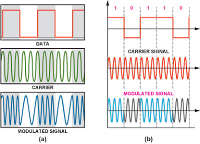
AM TRANSMITTER In an  AM  ( amplitude modulation )  transmitter  the amplitude (strength) of the carrier wave is varied in proportion to the modulation signal. In an FM (frequency modulation)  transmitter  the frequency of the carrier is varied by the modulation signal. There are two basic configuration for transmitters. High level modulation low level modulation  High level modulation In high power modulation signal,the carrier voltage is modulated at highest power level.the require power level is obtained by class c power amplifier.The block diagram of high level modulation as shown in fig(a). low level modulation In the low level modulation system, the carrier is modulated at low power level and the carrier power is subsequently raised to the desire level in the class B amplifier . transmitters using high power level are widely use at present .The block diagram of high level modulation as shown in fig(b). advantage AM sign

Frequency division multiplexing (fdm)

Image
Frequency-division multiplexing (FDM) is a scheme in which numerous signals are combined for transmission on a single communications line or channel. Each signal is assigned a different frequency within the main channel. Transmitter Receiver       Advantage •           It does not need synchronization between its transmitter and receiver. •          Frequency division  multiplexing is simpler and easy demodulation.. •          It is used for analog signals. •          A large number of signals (channels) can be transmitted simultaneously Disadvantage   It is suffers problem of cross-talk.   It is used only when a few low speed channels are desired.   Intermodulation distortion takes place.     Application •        It is used to public telephones and in cable TV systems. •       It is used in broad casting. •       It is used in AM and FM broadcasting. Video

TIME DIVISION MULTIPLEXING

Image
Time-division Multiplexing (TDM): It is also called synchronous TDM, which iscommonly used for multiplexing digitized voice stream. The users take turns usingthe entire channel for short burst of time. In frequency division multiplexing, all signals operate at the same time with different frequencies, but in Time-division multiplexing all signals operate with same frequency at different times. This is a base band transmission system, where an electronic commutator sequentially samples all data source and combines them to form a composite base band signal, which travels through the media and is being demultiplexed into appropriate independent message signals by the corresponding commutator at the receiving end. The in coming data from each source are briefly buffered. Each buffer is typically one bit orone character in length. The buffers are scanned sequentially to form a composite data stream. The scan operation is sufficiently rapid so that each buffer is emptied before more d

Psk modulation block diagram .

Image
Phase-shift keying (PSK) is a digital modulation scheme that conveys data by changing, or modulating, the phase of a reference signal (the carrier wave) any digital modulation scheme uses a finite number of distinct signals to represent digital data. PSK uses a finite number of phases, each assigned a unique pattern of binary digits. Usually, each phase encodes an equal number of bits. Each pattern of bits forms the symbol that is represented by the particular phase. BLOCK DIAGRAM                                                                                                                                                                 FIG.1                      APPLICATION It is use in bluetooth communications It is widely  use in wirless LANs. it us use in bio-metric system. ADVANTAGE It is more power efficient modulation techniques. high data transmission. psk is less susceptible to error than ASK,while it requires/occupies same bandwi

FREQUENCY SHIFT KEYING

Image
Frequency-shift keying  is the frequency modulation system in which digital information is transmitted through the discrete frequency change of a carrier wave. The technology is use in communication system.   such as amateur radio, caller ID, and urgent situation broadcasts. The simplest FSK is binary FSK (BFSK). BFSK uses a pair of discrete frequencies to transmit binary (0s and 1s) information. With this scheme, the “1” is called the mark frequency and the “0” is called the space frequency. FSK modulated wave shown in fig.1 ADVANTAGE It has low probability of error. It provide high signal to noise ratio (SNR). DISADVANTAGE  High power consume. High bandwidth. APPLICATION Radio transmission. Satellite link. VIDEO 

LOG PERIODIC ANTENNA

Image
LOG -PERIODIC ANTENNA The log periodic antenna show in fig 1.is a multiple - element antenna the uses an entirely different principle than that of the yagi antenna.It provides good gain and wide bandwidth ,although the achievable gain is not as high as a yagi can provide for the same as antenna.The log periodic antenna consists of an array of dipoles extended along a horizontal axis. The length of each dipole is shorter than the dipole preceding it.All dipoles are connected and transmission line is connected to the shortest dipole.Maximum radiation is from the small end. ADVANTAGE -wide bandwidth -same back to front ratio. -It is design to work across wide range frequency. DISADVANTAGE -The VSWR performance not so good. -low gain APPLICATION  -It is use in television -It is use to measure EMC (electromagnetic compatibility)  VIDEO OF LOG PERIODIC ANTENNA

satellite communication